The RTS151KEY(A) is capable of resetting only certain models of detec- tors. Refer to the detector installation instructions for additional information. Page 2 FIGURE 6. WIRING DIAGRAM FOR RTS151KEY(A) TO DH100 2-WIRE FIGURE 5.. Wiring Instructions Consult the appropriate detector installation instructions for the applicable wiring diagram. The RTS151KEY(-A) mounts to a single gang box (2.5˝ mini-mum depth), or directly to the wall or ceiling. In Canadian applications, the RTS151KEY(-A) is intended to be located in the

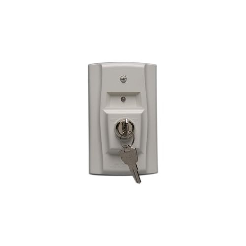


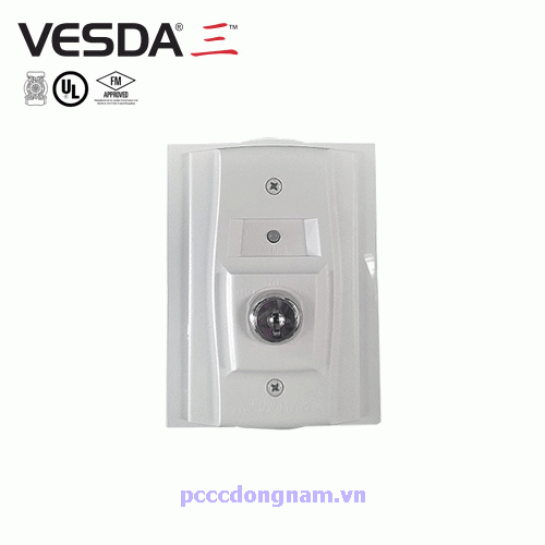


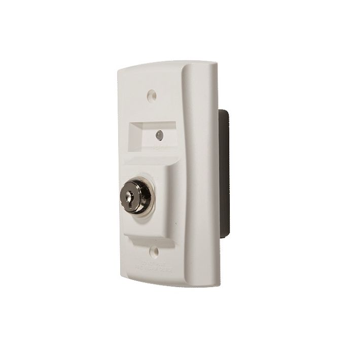

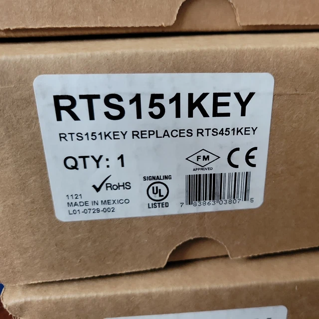
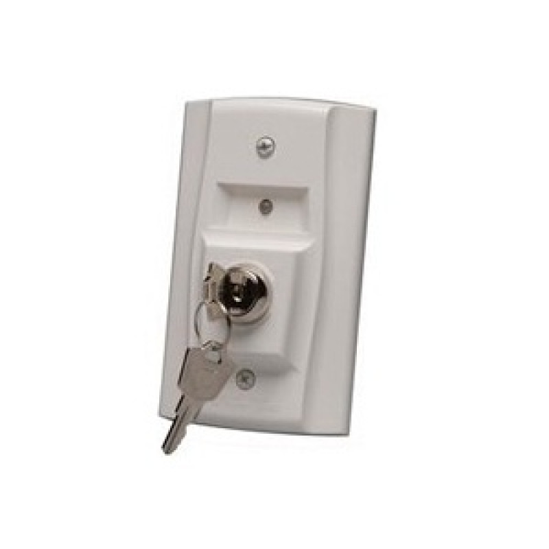
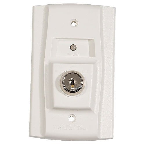

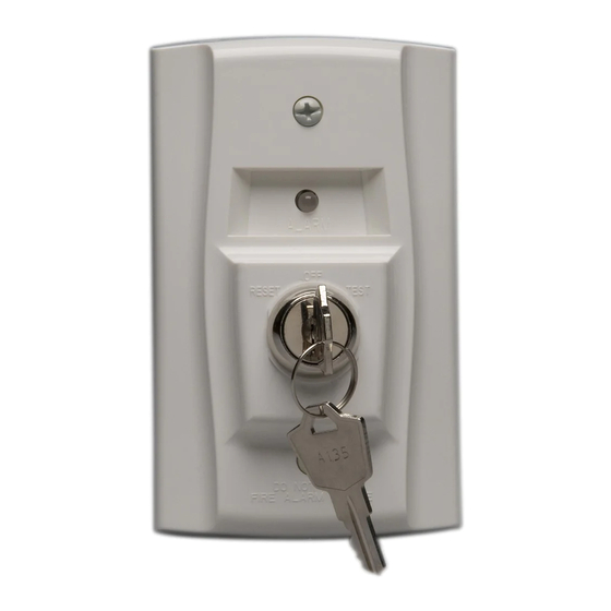

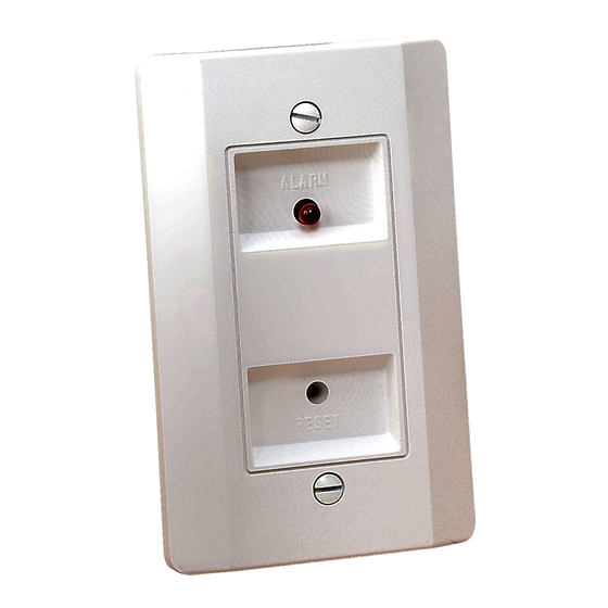




RTS151KEY(A) Remote Test Station INSTALLATION AND MAINTENANCE INSTRUCTIONS I56-0758-016 3825 Ohio Avenue, St. Charles, Illinois 60174 1.800.SENSOR2; Fax: 630.377.6495 www.systemsensor.com NOTE: RTS151KEY(A) replaces RTS451KEY. NOTICE: This manual shall be left with the owner/user of this equipment.. H0582-21 Figure 3: Wiring Diagram for RTS151KEY(A) to DNR 2-Wire Duct Smoke Detector WITH REMOTE TEST CAPABLE HEAD: Wiring Instructions Consult the appropriate detector installation instructions for the applicable wiring diagram. The RTS151KEY(A) mounts to a single gang box (2 1/2˝ minimum depth), or directly to the wall or ceiling.